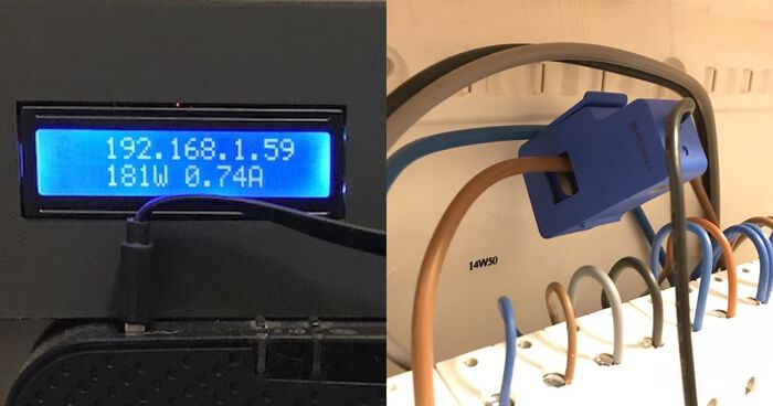
Home Energy Monitor: V2
My DIY home energy monitor has been running for almost a year now. It's been recording my electricity consumption every second and everything is neatly archived in my AWS account.
Still, though, there is room for improvement. It's time to look back, evaluate & improve the design. I've identified a few pain points that have to be fixed, so let's go!
Read more about Energy Monitor v1 here.
What could be improved
Out of all the things I could improve about V1, there is only one really critical thing:
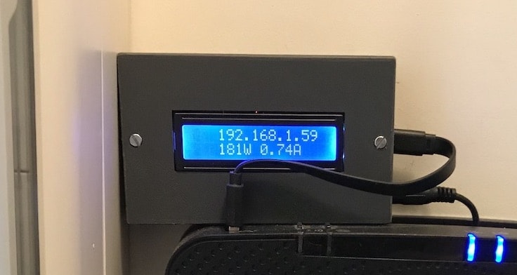
- WiFi stability: One of the main problems with the V1 was that it couldn't recover from a lost WiFi connection. I would walk past it and see an invalid IP address on its display:
0.0.0.0, meaning it had lost its WiFi connection, and a power cycle was needed to solve it. Aargh!
Then there were also some nice-to-haves:
- Better display: The LCD is okay to show basic information, but it isn't very fancy. It can only show two lines of 16 characters, and you can't draw custom shapes on it. It's also quite bulky and makes the whole unnecessarily large.
- DIN-rail mountable: Right now, my energy monitor sits on top of my internet router, which is conveniently mounted next to my electrical panel. I would prefer it if the energy monitor could be smaller so I could fit it on the DIN rail next to one of the circuit breakers.
- Better wiring: When I was building V1, I soldered the ESP32 directly onto a protoboard. I won't be making that mistake twice. It's nearly impossible (for me) to get the board off again.
- 12-bit ADC support: The ESP32 has a 12-bit ADC, but Emonlib (the library used to measure electricity consumption) only supports 10-bit. Bumping this up to 12-bit should increase the accuracy of the monitor.
Better display: ESP32 + OLED
I started my journey by looking for a new display. I found several small TFT panels on Adafruit that would work perfectly with the ESP32. But then I came across this beauty:
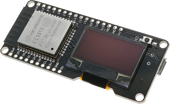
This is the NodeMCU ESP32 OLED Module, on some sites referred to as Wemos LOLIN32. It's an ESP32 development board with a built-in OLED display.
Microcontroller and display on the same board? That meant I didn't have to figure out how to mount a separate display in my enclosure and how to connect it to the ESP32. Yay!
Aside from these practicalities, it's also quite cheap. You can find different models on AliExpress that go for around €10.
The integrated OLED panel is 0.96" in size and has a resolution of 128x64. Not huge but perfect for this use case. While waiting for it to arrive, I broke out Sketch and started designing a simple user interface for it:
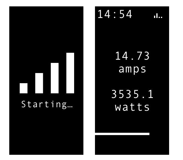
I decided to show the current time, the WiFi signal strength, the current electricity consumption, and a progress meter at the bottom. Progress of what? Well, the ESP32 takes one measurement each second and sends it to AWS after 30 seconds. The progress bar shows how close it is to sending a new batch to AWS ;)
Better wiring
After selecting the new hardware, it was time to adjust the wiring. While building the previous version, I soldered my ESP32 directly onto a protoboard. Bad idea! It's nearly impossible to remove the ESP32 from the protoboard. As a result: the ESP32 used in V1 will be lost forever. Thank god these microcontrollers are cheap.
So for V2, I purchased some female pin headers to solder onto the protoboard instead. This means I can now easily swap the ESP32 should it be necessary. Or I could decommission the energy monitor and re-use it for another project.
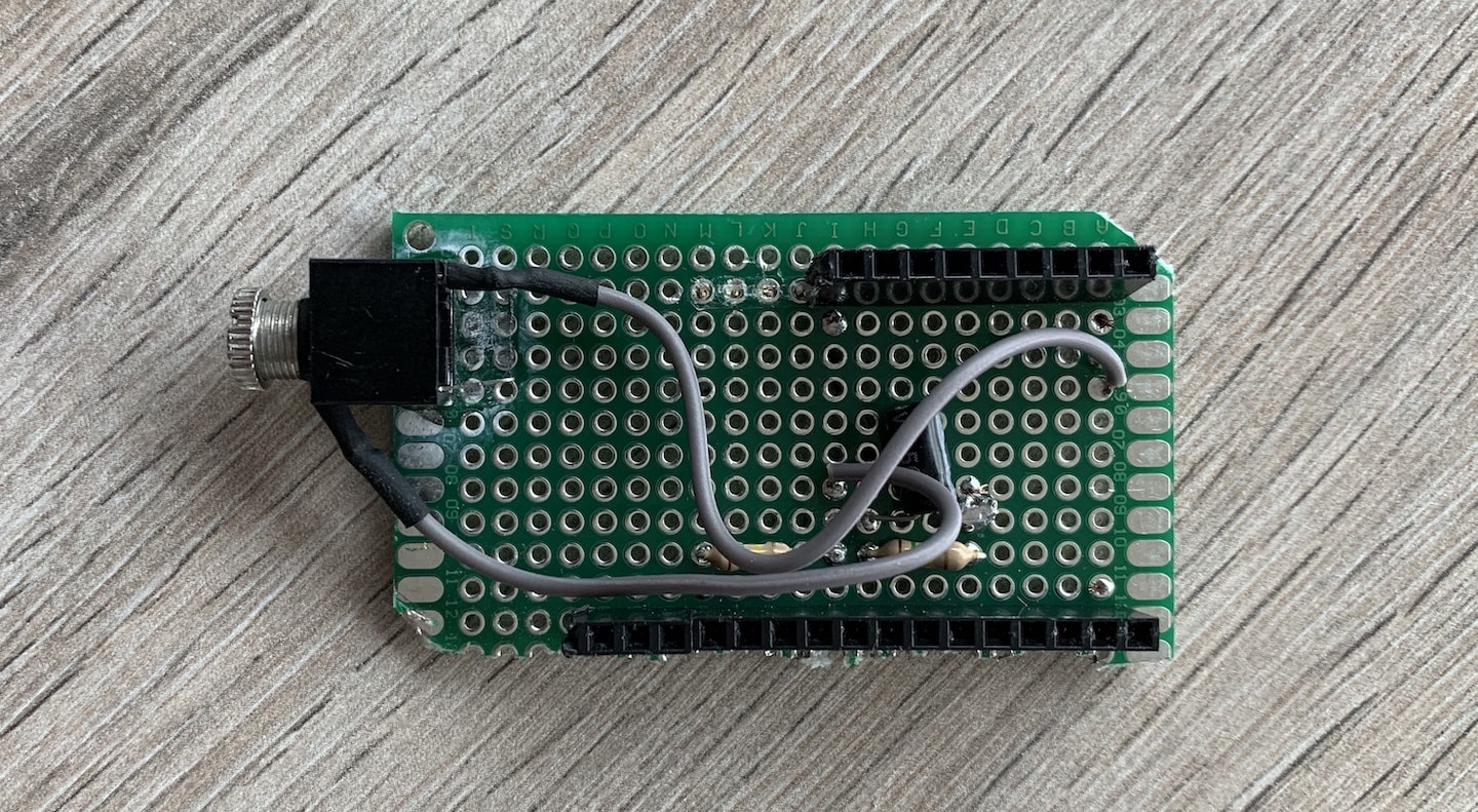
And here's how it looks with the ESP32 fitted onto the pin headers:
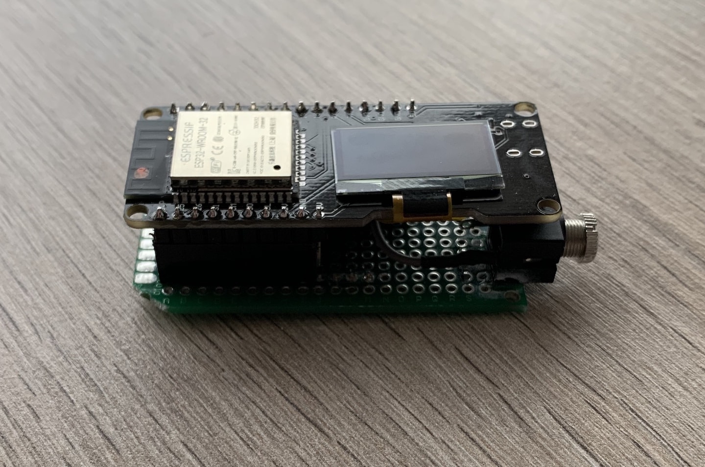
Improved stability: Arduino + FreeRTOS!
After improving the wiring, I started improving the software. The main issue with V1 was that it couldn't reconnect to the WiFi if it lost the connection. And because I'm using an unstable ISP-provided router, that happened quite often.
To fix this, I decided to use FreeRTOS, a system that allows you to create many tasks and let the scheduler worry about running them. I blogged about this before: Multitasking on ESP32 with Arduino and FreeRTOS
To solve my WiFi problem, I created a task that checks the connection every 10 seconds. WiFi still connected? Great, the task suspends itself for 10 seconds and then runs again. If it's disconnected, it will try to reconnect. Simple:
#include <Arduino.h>
#include "WiFi.h"

#define WIFI_NETWORK "YOUR-NETWORK-NAME"
#define WIFI_PASSWORD "YOUR-WIFI-PASSWORD"
#define WIFI_TIMEOUT 20000 // 20 seconds

/**
 * Task: monitor the WiFi connection and keep it alive!
 *
 * When a WiFi connection is established, this task will check it every 10 seconds
 * to make sure it's still alive.
 *
 * If not, a reconnect is attempted. If this fails to finish within the timeout,
 * the ESP32 is sent to deep sleep in an attempt to recover from this.
 */
void keepWiFiAlive(void * parameter){
    for(;;){
        if(WiFi.status() == WL_CONNECTED){
            vTaskDelay(10000 / portTICK_PERIOD_MS);
            continue;
        }

        Serial.println("[WIFI] Connecting");

        WiFi.mode(WIFI_STA);
        WiFi.setHostname(DEVICE_NAME);
        WiFi.begin(WIFI_NETWORK, WIFI_PASSWORD);

        unsigned long startAttemptTime = millis();

        // Keep looping while we're not connected and haven't reached the timeout
        while (WiFi.status() != WL_CONNECTED &&
                millis() - startAttemptTime < WIFI_TIMEOUT){}

        // If we couldn't connect within the timeout period, retry in 30 seconds.
        if(WiFi.status() != WL_CONNECTED){
            Serial.println("[WIFI] FAILED");
            vTaskDelay(30000 / portTICK_PERIOD_MS);
			  continue;
        }

        Serial.println("[WIFI] Connected: " + WiFi.localIP());
    }
}
To start this task, I use:
// ----------------------------------------------------------------
// TASK: Connect to WiFi & keep the connection alive.
// ----------------------------------------------------------------
xTaskCreatePinnedToCore(
    keepWiFiAlive,
    "keepWiFiAlive",  // Task name
    10000,            // Stack size (bytes)
    NULL,             // Parameter
    1,                // Task priority
    NULL,             // Task handle
    ARDUINO_RUNNING_CORE
);
This task has solved my WiFi connectivity issue! And thanks to FreeRTOS, I don't have to worry about when to run this code. I just rely on the scheduler to run it every 10 seconds.
12-Bit ADC compatibility
While I was improving the software, I also remembered that Emonlib - the library which converts raw readings into amps - only supports a 10-bit ADC, while the ESP32 has a 12-bit one.
It doesn't seem like a big deal until you realize that 10-bit ADC's have a range of 0-1024, while 12-bit ones go up to 4096. That's four times the range, and so it's four times more accurate.
To fix this, I forked Emonlib and create a version specifically for the ESP32: https://github.com/Savjee/EmonLib-esp32
I then added it as a dependency to my PlatformIO project (in platformio.ini):
lib_deps =
  https://github.com/Savjee/EmonLib-esp32.git
I only changed the implementation of the calcVI and calcIrms functions. Their signatures remain the same, so the rest of my code could stay the same.
Smaller case & DIN rail
Next step: adapting the case. It could be made a lot smaller because the display is now integrated into the microcontroller. Additionally, I wanted the option to put it on a DIN rail (a standardized way of mounting electrical hardware such as circuit breakers).
A DIN-rail mount would allow me to put the energy monitor inside my breaker box. In Belgium, our breaker boxes usually have transparent covers so you can see each breaker, which is ideal for making the OLED visible.
Just like last time, I designed the case in Fusion360. I opted to go for a design where the back could be swapped out for different models:
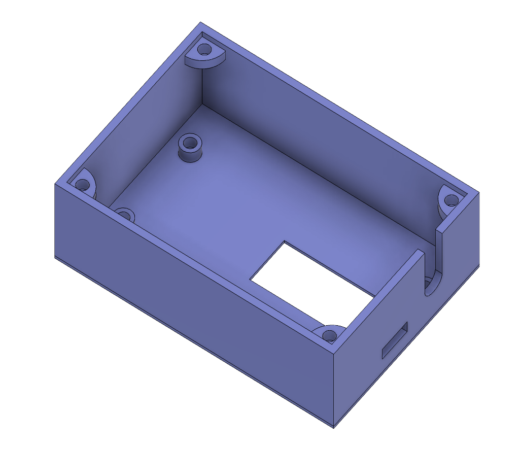
There are cutouts for the OLED display, the micro-USB port, and the headphone jack that connects the CT sensor. I also added standoffs for the ESP32 so I can securely screw it into place. For the top lid, I designed four standoffs located in the corners of the case. They have a 45° tapered angle so that they can be 3D printed.
After designing the enclosure, I designed two versions of the top lid. One flat one (which I'm currently using) and one with a DIN rail mount:
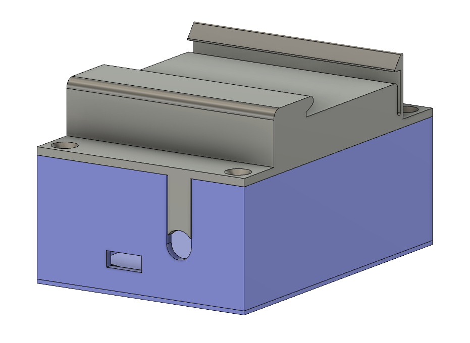
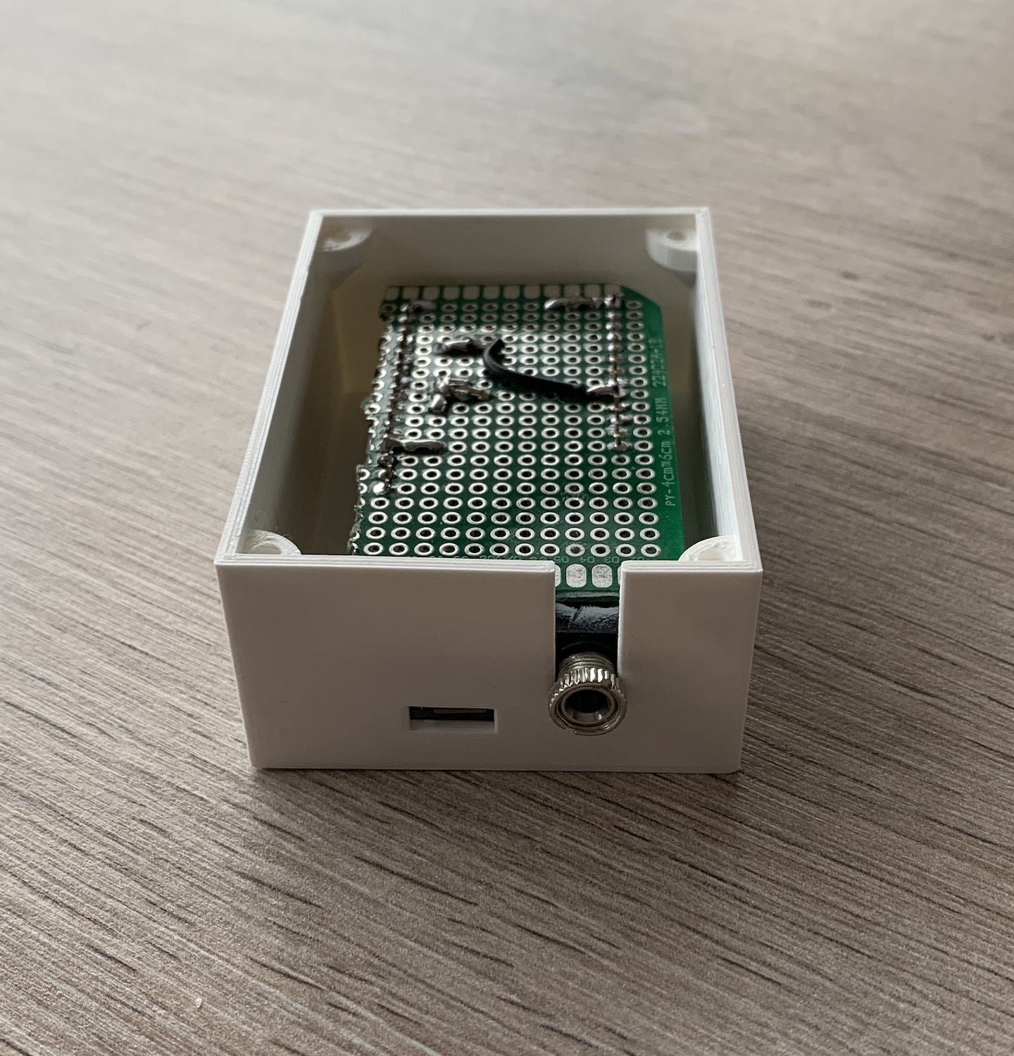
After tweaking some of the margins, it was time to assemble everthing. Starting by screwing the ESP32 into the base of the case:
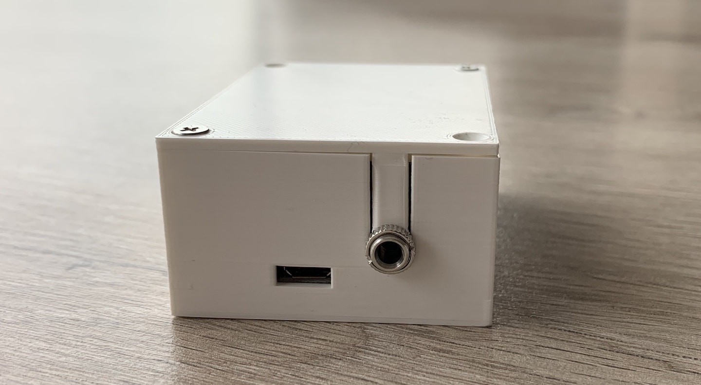
Putting on the top lid (without DIN-rail for now):
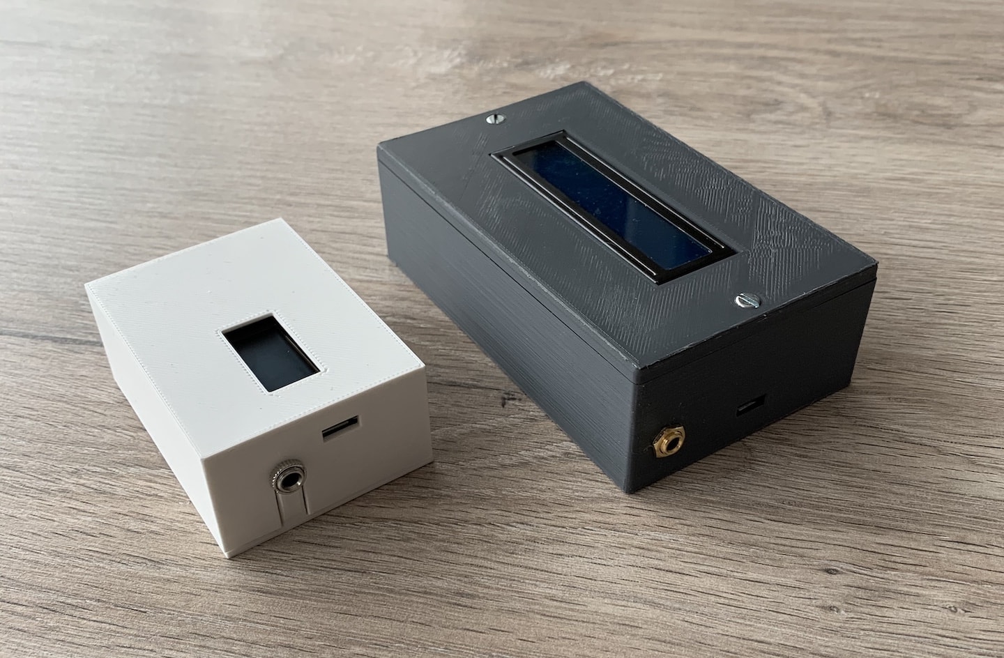
In comparison to the V1:
Cloud architecture
While it hasn't been changed, I want to mention the cloud infrastructure as well. Here is an overview of what I have running currently:
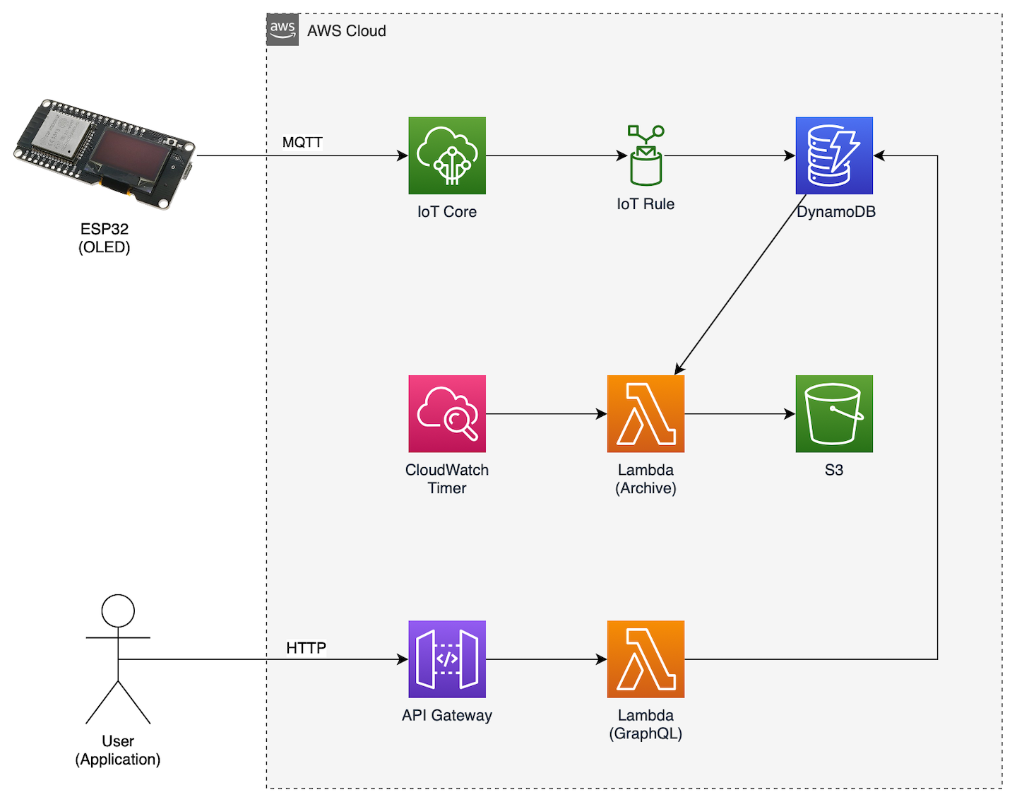
In a nutshell:
- I'm using AWS IoT Core to connect my ESP32 to the cloud (it's basically an MQTT broker with fancy features).
- An IoT Rule is trigged every time my energy monitor sends a message to AWS. The rule writes each message to a DynamoDB table. I'm using the device's ID as the primary key and the timestamp as the sort key.
- Every night, CloudWatch triggers a Lambda function that gets yesterday's readings from DynamoDB, puts them in a CSV file, and archives them to S3. I've added Gzip compression to this step to keep storage costs low.
- A second Lambda function exposes a GraphQL API that is consumed by the web dashboard and the Ionic app.
Integrating with Home Assistant
I've been a huge fan of Home Assistant, ever since a colleague of mine introduced me to it. I have it running on a Raspberry Pi that is booting from an external SSD.
Naturally, I wanted my energy consumption to show up there as well. So that means the ESP32 has to connect to two services: AWS (to archive all my readings) and Home Assistant.
You can interface with Home Assistant in a number of ways. I decided to use MQTT because I already know how to use it on the ESP32. The only requirement is that you install a broker (or use an online service) on your Home Assistant machine. I chose to use the Mosquito integration of HASS.IO.
Home Assistant gives device makers two options to integrate with MQTT: either the user has to configure the device manually in the configuration.yaml file, or the device can configure itself by using MQTT Discovery.
Of course, I choose the latter -- no manual configuration for me.
To make it all work, you have to tell Home Assistant everything there is to know about your device. The name, type, measurement units, the icon, and so on... This can be done by posting a message to this MQTT topic: homeassistant/sensor/home-energy-monitor-1/config with the following contents:
{
    "name": "home-energy-monitor-1",
    "device_class": "power",
    "unit_of_measurement": "W",
    "icon": "mdi:transmission-tower",
    "state_topic": "homeassistant/sensor/home-energy-monitor-1/state",
    "value_template": "{{ value_json.power }}",
    "device": {
        "name": "home-energy-monitor-1",
        "sw_version": "2.0",
        "model": "HW V2",
        "manufacturer": "Xavier Decuyper",
        "identifiers": ["home-energy-monitor-1"]
    }
}
This will automatically configure my energy monitor in Home Assistant and even adds it to the device registry. No additional work required!
All that's left now is to periodically send the energy consumption to the topic homeassistant/sensor/home-energy-monitor-1/state:
{ "power": 163 }This is the end result:
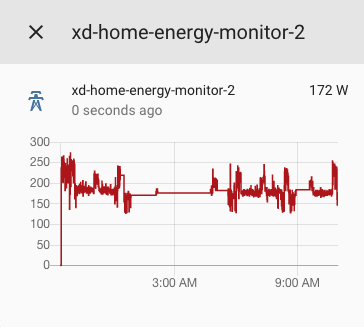
Note: Home Assistant integration is optional and disabled by default in the firmware. If you want to enable it, open the config.h file, set HA_ENABLED to true and enter the IP address of your Home Assistant instance as well as the login credentials for your MQTT broker.
Status & next steps
I've been running V2 of my energy monitor since January 3th, 2020, and so far, it's been rock solid. The WiFi and MQTT connections are automatically reconnected if necessary. That's already a huge improvement.
In terms of next steps, I only have three:
- Print & test the DIN rail mount
- Design & order a custom PCB to replace the protoboard and my bad soldering skills ;)
Integrate it with my Home Assistant installation
So stay tuned for an update ;)
A note on calibration
The SCT013 sensors aren't very accurate with low current. You might see "idle" readings of a couple of watts even though no current is flowing through the wire.
According to Jm Casler, this is caused by
- The SCT013 is built for price, not for quality
- The cable's shielding can induce noise if it's shorted with the signal cable
- A filter capacitor is needed (preferably a ceramic one)
You can read his full (detailed) analysis here: https://www.casler.org/wordpress/low-current-measurement-performance-of-the-sct013/.
Additionally, he shared the formula that he uses to calculate the calibration value for emonlib:
Calibration number = Number of turns of CT Clamp / Burden Resistor
So for a CT clamp with 2000 turns and a 68-ohm burden, that gives a calibration of 29.4.
Thanks, man!
Source code
All of the source code for this project is available on GitHub. That includes the ESP32 firmware, the AWS Lambda functions (and Serverless configuration file) as well as the Fusion360 design files.

